Pump Curves And System Curves
Pump curves and system curves. If your cow sounds like this may we suggest the fish. System head curves can be a valuable tool for analyzing pumping systems with different pumps multiple or variable head conditions multiple pump speeds or various impeller trims on the same sheet of paper. AFT software accounts for these differences and can use a Traditional or Enhanced method according to user preference to develop the desired curve.
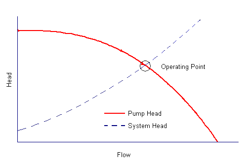
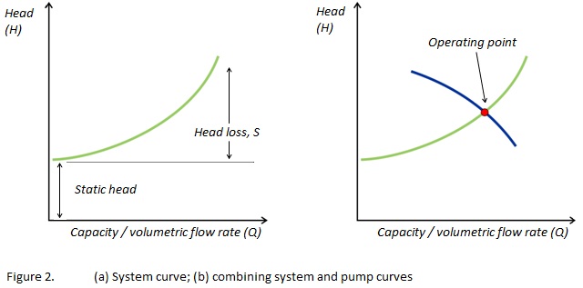
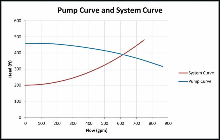
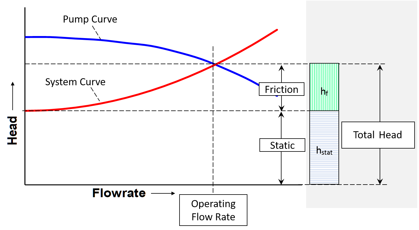
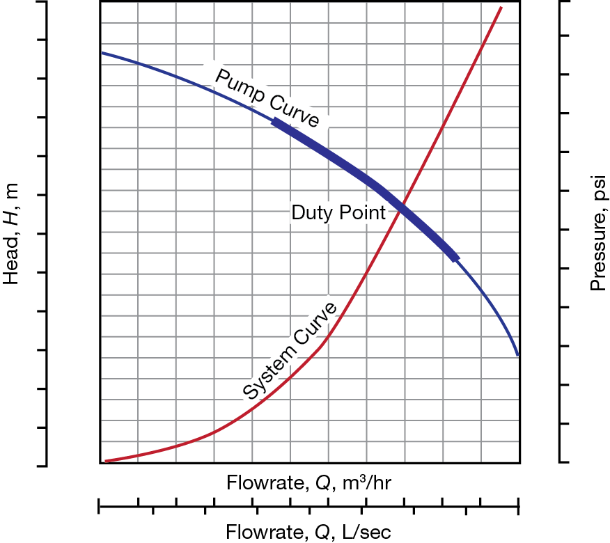
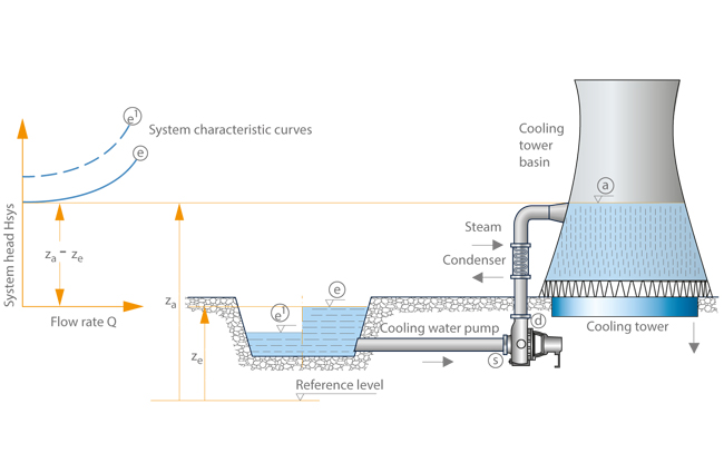
In the pumping system there are two characteristic curves that determine the operating point of the pump. The pressure is related to the square of the velocity. You can also generate a combined pump curve where pumps are either in parallel or series.
How to read a pump curve. A fixed duct system has one and only one system curve. Would you like to see how fast and easy it can be to draw one given just two pieces of in.
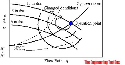
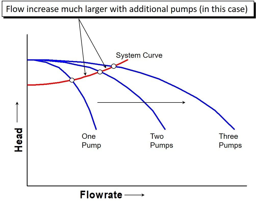
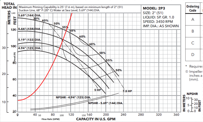
System curve calculation can become more complex when there are multiple pumps in parallel or in series especially when there are different pump curves for each pump. The greater the pumps range of impeller size options the more curves will be shown. They are adaptable for low or high head conditions multiple flow conditions or with one or more pumping units.
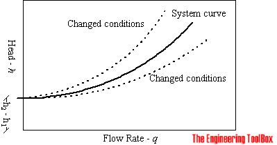
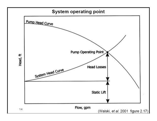
Changing something in the ductwork creates a new duct system with a new system curve. The pump curve has a downward negative slope since produced head declines as flow increases. The way that AFT Fathom generates the system curve is that it will take the model into the background as it generates the system curve and it modifies the pump to a pseudo-fixed flow pump.
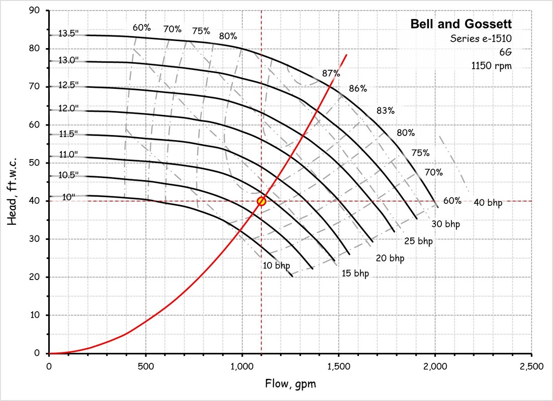
Shutoff Best Efficiency Point BEP and runout. One is related to the pump itself which is called the pump characteristic curve and the other is related to the system and components before and after the pump which is called the system characteristic curve. Pump performance curves give you the information you need to choose the right pump for your application.
This method works for a system consisting of a single source of fluid single pump and single destination. For details about calculation NPSH Available refer to EnggCyclopedias solved sample problem.
One is related to the pump itself which is called the pump characteristic curve and the other is related to the system and components before and after the pump which is called the system characteristic curve.
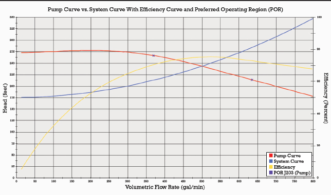
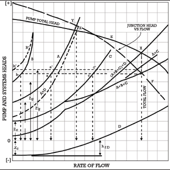
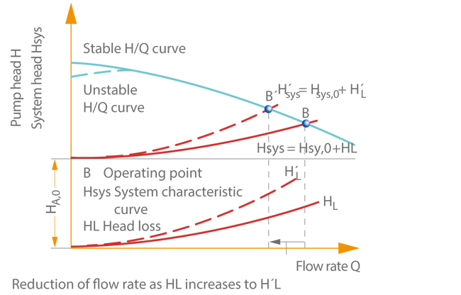
System curve calculation can become more complex when there are multiple pumps in parallel or in series especially when there are different pump curves for each pump. In my last column Tips for Proper Pump Selection Pumps Systems May 2016 read it here I briefly mentioned drooping pump curves and stated that I would spend time in a future article discussing the subject. Pumping System Head CM3215 FAM 3Mar2014 9 17 æ ì æ ç Ø à 3is the system head curve H ft Q galmin system curves æ ì æ ç Ø à L 3 6 E System Head -. You can also generate a combined pump curve where pumps are either in parallel or series. One of the variants that will add multiple curved lines when reading a pump curve is the impeller size. Did you ever struggle with the complexities of pump system curves. In my opinion the system curve is the single most important component of the pump selection process. The system curve is even more important when an application requires multiple. System head curves can be a valuable tool for analyzing pumping systems with different pumps multiple or variable head conditions multiple pump speeds or various impeller trims on the same sheet of paper.
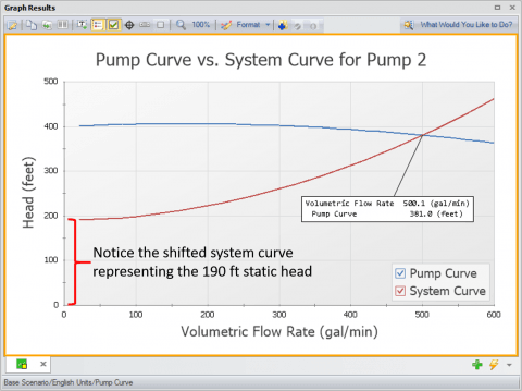
System Curves raphical representation of the relationship between discharge and head loss in a system of pipes The system curve is completely independent of the pump characteristics The basic shape of the system curve is parabolic because the the head loss equation and on the velocity head term is 20 or nearly 20 The system curve will start at zero flow and zero head if there is. In the future well discuss means of controlling the flow rate along with the limitations of a system curve and explore ways to see how to visualize more complex piping systems. Using a pump curve find the operating point of a system and determine the power required to run the pump. The system curve tool in MEboost can generate a fluid system curve approximation as well as up to four pump curves on the same chart. A drooping pump curve is a characteristic head-flow pump performance curve that does not continually rise when moving from the best efficiency point BEP back to shutoff. The pump curve has a downward negative slope since produced head declines as flow increases. In this article well show how calculations are made and how to generate the system and pump curves in MEboost.



















Post a Comment for "Pump Curves And System Curves"